1. The listing, audited
The page is called Core-Drill-Bits in the URL, Vacuum Brazed Diamond Core Drill Bits in the title and the H1, and Core Drill Bits in the category trail. Three names for one product, and the range already has two other pages called vacuum brazed core drill bits — one selling sets, one selling a single set. Before anything else, the naming has to be fixed, because a buyer comparing three near-identical titles cannot tell which one is the single bit.
| What the listing says | What is wrong | What to write instead |
|---|---|---|
| Title: Vacuum Brazed Diamond Core Drill Bits | Identical in substance to the title of the set page and the single-set page. In a search result the three are indistinguishable, and the set pages will win because they mention a set in the title. | Vacuum Brazed Diamond Core Drill Bits, 5–70 mm, Single Bits — keep “single” or the size range in the title. |
| Table row 25HVBCB: diameter 15 | The item number encodes the diameter everywhere else in the table, and 25HVBCB is listed against 15 mm. One of the two is a transcription error. | 25 mm, confirmed against the physical bit. Do not let a buyer order from a table that contradicts itself. |
| Fast and smooth, long lifespan, high efficiency | No comparator and no unit. Long compared with what, on which material, at what feed? | Holes per bit in a named material, or the cutting time for a named thickness. One measured number beats three adjectives. |
| Dry cutting, wet cutting | Both are possible, but on a single-layer tool they are not equivalent. Dry running removes the only cooling the layer has, and the layer has no thickness to lose before it is gone. | Wet for porcelain, stone and granite. Dry only on soft wall tile, with extraction and a light feed. |
| Good concentricity | Concentricity is an assembly result, not a feature. It is decided by the socket thread or the shank seat and by the machine spindle, and it matters most on the smallest bit, where the same runout is a larger share of the diameter. | State the runout of the barrel to the shank, and the maximum recommended runout at the spindle. |
| Applicable to porcelain, ceramic, granite, marble, stone brick, ceramic tile | These span a factor of five in abrasiveness. A single-layer bit that is right for porcelain is wrong for granite, and the sentence gives the buyer no way to know which end they are buying. | Split by what the layer is specified for, and say plainly that concrete is a different tool. |
| Missing entirely | Wall thickness, diamond grit size, number and size of the chip holes, and the fact that the 25 mm is a cutting-ring height rather than a total depth capability. | All four. The chip holes in particular are the reason the depth stops where it does. |
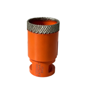
The listing does have one genuine strength that most competitors bury: it prints the thread options as a list rather than a single figure. M14, M16, 5/8-11 and 1/2 GAS in one table row tells a distributor that the same barrel is machined for four markets, which is exactly what an export buyer wants to know.
2. The depth is set by a hole in the side
A segmented core bit sheds its cuttings through the gaps between the segments. Those gaps run the full height of the crown, so as the bit goes deeper the cuttings still have a short radial path to the outside. A continuous brazed ring has no gaps at all. The rim is one unbroken band of diamond, so the only way out is upward, along the annulus between the core and the inside of the barrel, and then out through the holes cut in the barrel wall.
That changes what limits the depth. It is not the diamond, and it is not the strength of the steel. It is the height at which the exit stops being an exit.
| Depth reached | Where the side holes are | What the chip can do | What the operator feels |
|---|---|---|---|
| 0–10 mm | Above the surface, fully open | Leaves radially and is thrown clear or carried by water | Fast, quiet, clean edge |
| 10–20 mm | Partially in the hole, still open to the surface side | Leaves, but has to turn a corner | Slightly slower, water goes cloudy |
| 20–25 mm | At the surface line, half buried | Leaves only if the flow is strong enough to carry it round the turn | Feed needs steady pressure; easing off produces no cut |
| 25–35 mm | Inside the hole, facing the wall | Cannot leave radially; packs the annulus and the barrel | Bit stops cutting, motor loads, water stops returning |
| beyond 35 mm | Deep inside, blocked by the core and the wall | No path at all | Jam, then heat, then a spent layer |
This is why the number is 25 and not 70. The 70 mm is a handling dimension: it is the length that lets a socket, a shoulder and a 10 mm shank sit behind a 25 mm ring. Reading it as capacity is the single most common mistake on this product, and it is the mistake the listing invites by printing the two numbers side by side with no explanation.
3. Two holes against an annulus
Once the exit is the only route, its size becomes a design limit. The barrel carries two elongated holes, and their combined area can be compared with the cross-section of the annulus they have to clear. If the holes are larger than the annulus, the exit is never the bottleneck and the limit is purely geometric — the depth at which the holes are buried. If the holes are smaller than the annulus, they throttle the flow even before they are buried.
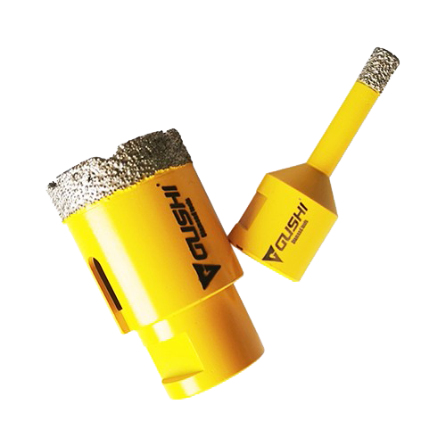
The two holes on this barrel are elongated slots rather than circles, which is the right choice for chip clearance: an elongated hole has more area for the same weakening of the tube, and it presents a longer opening along the direction the chips are travelling. Taking the pair at roughly 96 mm² of combined area — a figure that should be measured on the goods rather than trusted — the ratio behaves like this.
| Diameter | Assumed wall | Annulus cross-section | Hole area | Ratio | What it means |
|---|---|---|---|---|---|
| 5 mm | 0.9 mm | 14 mm² | 96 mm² | 6.8 × | Exit is wide open; the limit is the 5:1 hole geometry |
| 6 mm | 0.9 mm | 17 mm² | 96 mm² | 5.7 × | Open |
| 8 mm | 0.9 mm | 23 mm² | 96 mm² | 4.2 × | Open |
| 10 mm | 0.9 mm | 28 mm² | 96 mm² | 3.4 × | Open |
| 12 mm | 0.9 mm | 34 mm² | 96 mm² | 2.8 × | Open |
| 14 mm | 1.1 mm | 48 mm² | 96 mm² | 2.0 × | Comfortable |
| 16 mm | 1.1 mm | 55 mm² | 96 mm² | 1.7 × | Comfortable |
| 18 mm | 1.1 mm | 62 mm² | 96 mm² | 1.5 × | Fine |
| 20 mm | 1.1 mm | 69 mm² | 96 mm² | 1.4 × | Fine |
| 25 mm | 1.1 mm | 86 mm² | 96 mm² | 1.1 × | Marginal; flow depends on water pressure |
| 30 mm | 1.1 mm | 104 mm² | 96 mm² | 0.9 × | Holes are now smaller than the annulus |
| 32 mm | 1.1 mm | 111 mm² | 96 mm² | 0.9 × | Throttled |
| 35 mm | 1.1 mm | 121 mm² | 96 mm² | 0.8 × | Throttled |
| 40 mm | 1.1 mm | 138 mm² | 96 mm² | 0.7 × | Throttled; pecking is mandatory |
| 45 mm | 1.1 mm | 156 mm² | 96 mm² | 0.6 × | Throttled |
| 50 mm | 1.1 mm | 173 mm² | 96 mm² | 0.6 × | Throttled |
| 55 mm | 1.1 mm | 190 mm² | 96 mm² | 0.5 × | Throttled |
| 60 mm | 1.1 mm | 207 mm² | 96 mm² | 0.5 × | Throttled |
| 65 mm | 1.1 mm | 225 mm² | 96 mm² | 0.4 × | Badly throttled |
| 70 mm | 1.1 mm | 242 mm² | 96 mm² | 0.4 × | Badly throttled; two holes are not enough |
The crossover sits at about 27.8 mm — the diameter at which the annulus cross-section equals the combined hole area. The range steps from 25 mm straight to 30 mm, so the ladder jumps over the crossover rather than landing on it. That is good product design: there is no size in the catalogue that sits exactly on the threshold and therefore works or fails depending on the batch.
Why the holes are elongated
A round hole of the same area would need a larger diameter, and a larger diameter removes more of the tube’s circumference at the point where the bending load is highest. An elongated slot spreads the same opening along the barrel axis, keeps more of the hoop continuous, and gives the chip a longer edge to slide along. It is the standard solution on thin-wall brazed barrels, and it is why the two openings look like slots rather than ports.
4. The same 25 mm is twenty different holes
Every size in this range cuts 25 mm deep. Printed as one column, that reads as a uniform capability. Measured against the diameter, it is anything but: the hole at 5 mm is five diameters deep, and the hole at 70 mm is a third of a diameter deep. Those are not the same operation performed at different sizes; they are two different problems that happen to share a number.
| Diameter | Depth ÷ diameter | Core left behind | Material removed | What actually limits it |
|---|---|---|---|---|
| 5 mm | 5.00 | 3.2 mm | 353 mm³ | The core snaps; the chip gap is 0.9 mm wide and 25 mm long |
| 6 mm | 4.17 | 4.2 mm | 424 mm³ | Same, slightly relieved |
| 8 mm | 3.13 | 6.2 mm | 565 mm³ | Clearance, with a core that still breaks easily |
| 10 mm | 2.50 | 8.2 mm | 707 mm³ | Clearance |
| 12 mm | 2.08 | 10.2 mm | 848 mm³ | Clearance; the practical start of comfortable coring |
| 14 mm | 1.79 | 11.8 mm | 1,210 mm³ | Balanced |
| 16 mm | 1.56 | 13.8 mm | 1,382 mm³ | Balanced |
| 18 mm | 1.39 | 15.8 mm | 1,555 mm³ | Balanced |
| 20 mm | 1.25 | 17.8 mm | 1,728 mm³ | Balanced; the sweet spot of the range |
| 25 mm | 1.00 | 22.8 mm | 2,160 mm³ | Hole area now equal to the side holes; flow starts to matter |
| 30 mm | 0.83 | 27.8 mm | 2,592 mm³ | Side holes smaller than the annulus |
| 32 mm | 0.78 | 29.8 mm | 2,765 mm³ | Throttled |
| 35 mm | 0.71 | 32.8 mm | 3,024 mm³ | Throttled; pecking required |
| 40 mm | 0.63 | 37.8 mm | 3,456 mm³ | Throttled; water flow becomes the control |
| 45 mm | 0.56 | 42.8 mm | 3,888 mm³ | Clearance limited |
| 50 mm | 0.50 | 47.8 mm | 4,320 mm³ | Clearance limited |
| 55 mm | 0.45 | 52.8 mm | 4,752 mm³ | Clearance limited |
| 60 mm | 0.42 | 57.8 mm | 5,184 mm³ | Clearance limited |
| 65 mm | 0.38 | 62.8 mm | 5,616 mm³ | Clearance limited |
| 70 mm | 0.36 | 67.8 mm | 6,048 mm³ | Clearance limited, at 17 times the volume of the 5 mm |
Read the third column: the core that the smallest bit leaves is 3.2 mm across. That is thinner than the wall of most copper pipe. It is a 25 mm long column of porcelain or marble at a 7.8:1 slenderness, held at one end by material it is bonded to and at the other by nothing at all. It will break on the way out, and when it does the fragment sits in the barrel and the next advance bears on the fragment instead of on the material.
Read the last column: the largest bit removes seventeen times the volume of the smallest, in the same depth, and it removes it through two holes that are now less than half the area of the annulus they serve. The two ends of one catalogue line have almost nothing in common.
5. The small end: a 3.2 mm core
Below about 12 mm, three effects arrive at once and they all push in the same direction: do less per pass.
- The core is fragile. A 3.2 mm column of tile or stone 25 mm long breaks under its own bending when the barrel is withdrawn at an angle. Once broken, it cannot be cleared by water alone.
- The chip path is extreme. The gap between core and barrel is the wall thickness, about 0.9 mm, and it is 25 mm long. That is a channel 28 times longer than it is wide, which is why a small brazed bit produces paste rather than chips if the water is marginal.
- Force has nowhere to go. The cutting area is only 14 mm² at 5 mm, so the same hand pressure that suits a 20 mm bit will overload the edge and burn the single layer instead of cutting.
| Diameter | Cutting area | Feed that suits it | Water | Rhythm |
|---|---|---|---|---|
| 5 mm | 14 mm² | 0.5–0.8 mm/s, feather light | Steady, low volume, aimed at the gap | Advance 2–3 mm, withdraw, repeat; never lean on it |
| 6 mm | 17 mm² | 0.6–0.9 mm/s | Steady | Advance 3 mm, withdraw |
| 8 mm | 23 mm² | 0.8–1.1 mm/s | Steady | Advance 4 mm, withdraw |
| 10 mm | 28 mm² | 1.0–1.3 mm/s | Steady, visible return | Advance 5 mm, withdraw |
| 12 mm | 34 mm² | 1.1–1.5 mm/s | Visible return at the hole | Advance 6–8 mm, withdraw |
The rhythm matters more than the speed at these sizes. A 5 mm bit that is advanced 2 mm and withdrawn four times will finish the hole in less time than one that is leaned on continuously, because the second one spends most of its life cutting its own packed cuttings.
Why the smallest sizes are not really core drills
At 5 mm the core is 3.2 mm. Nobody keeps a 3.2 mm plug: it is waste, and it is the part that causes the jam. So the tool is being used as a hole saw with a very thick wall rather than as a coring tool. That is fine — it is what the job needs for a cable gland or a fixing — but it explains why the rules that work for a 40 mm core bit do not transfer. On a 40 mm bit the plug is the product; on a 5 mm bit it is the problem.
6. The large end: rim speed and power
The intuition is that a 70 mm bit needs a big motor. It does not, because the wall is thin. What it needs is a slow spindle and a lot of clearing. Cutting power is the annulus area times the feed times the specific energy; with a 1.1 mm wall the area at 70 mm is 242 mm², and at a realistic feed for a single layer that is a few hundred watts, not kilowatts.
| Diameter | rpm for a 4 m/s rim | Cutting power at 1.5 J/mm³ | Input at 60% | What to watch |
|---|---|---|---|---|
| 20 mm | 3,800 | 125 W | 210 W | Nothing much |
| 25 mm | 3,040 | 155 W | 260 W | Water return |
| 30 mm | 2,530 | 185 W | 310 W | First size where the holes throttle |
| 35 mm | 2,170 | 215 W | 360 W | Packing |
| 40 mm | 1,900 | 245 W | 410 W | Packing, edge chipping on exit |
| 50 mm | 1,520 | 305 W | 510 W | Packing, water volume |
| 60 mm | 1,270 | 365 W | 610 W | Packing, runout of the machine |
| 70 mm | 1,090 | 430 W | 715 W | Packing first, then heat |
Those power figures assume a feed that a single layer can sustain, which is well below what a segmented bit would take. That is the point: the thin wall means the tool is not power-hungry, so the failure at the large end is not a stall. It is a barrel that fills up and then runs dry against its own cuttings, which is a heat failure dressed up as a power problem.
Runout is a diameter problem too
A machine with 0.1 mm of runout at the spindle puts the same 0.1 mm on every bit. On a 20 mm bit that is 0.5% of the diameter and invisible. On a 5 mm bit it is 2%, which is enough to widen the hole, load one side of the ring and wear the layer unevenly. This is why the smallest sizes are the ones that expose a tired chuck, and why the listing’s claim of good concentricity belongs with a number rather than an adjective.
7. What 25 mm buys in material
The depth is the whole specification for a buyer, because it decides which jobs the tool can do at all. Twenty-five millimetres is generous for tile and tight for worktops, and the difference is not something the diameter tells you.
| What you are drilling | Typical thickness | Passes | Margin left | Verdict |
|---|---|---|---|---|
| Ceramic wall tile | 6–10 mm | 1 | 15–19 mm | Comfortable; the natural job for this bit |
| Porcelain floor tile | 8–12 mm | 1 | 13–17 mm | Comfortable; wet, light feed |
| Ultra-compact surface | 6–12 mm | 1 | 13–19 mm | Works, but a thin-wall bit made for the material is better |
| Marble or limestone slab | 20 mm | 1 | 5 mm | Works; watch the exit |
| Quartz surface | 20 mm | 1 | 5 mm | Works; slow feed, plenty of water |
| Quartz or granite worktop | 30 mm | 2, or turn the work | None | Second pass; alignment is now the risk |
| Granite worktop with a bullnose | 30–40 mm | 2–3 | None | Use a deeper bit; this is the wrong tool |
| Glass | 6–12 mm | 1 | 13–19 mm | Possible with a fine grit and flood water; a purpose-made bit is safer |
| Brick or block wall | 100–240 mm | Not applicable | — | Wrong tool: too shallow, too fine, wrong bond |
| Reinforced concrete | 100 mm and up | Not applicable | — | Wrong tool: a single layer chips on aggregate and rebar |
The boundary that catches people is the worktop. A 20 mm slab is a single comfortable pass; a 30 mm slab is two passes, and two passes on a polished surface means the second one starts in a hole whose edge is already chamfered by the first. The bit will do it. The finish will show it.
8. A ring, not a crown
Most core bits in this catalogue are built from segments: separate blocks of diamond and metal, welded or sintered around the end of a tube, with gaps between them. This one is a continuous band of brazed diamond. The difference is not cosmetic, because the gaps in a segmented crown are also the chip path.
| Continuous brazed ring (this bit) | Segmented laser-welded crown | Sintered thin-wall crown | |
|---|---|---|---|
| Chip path | Up the annulus, out through side holes in the barrel | Through the gaps between segments, radially | Through narrow slots cut across the rim |
| Kerf width | Narrow, roughly wall plus grit | Wider, set by the segment | Narrow, set by the wall |
| Cut feel | Continuous and smooth; no impact | Slight rhythm as each segment engages | Smooth, but sensitive to feed |
| Edge quality on tile | Best of the three | Good, with more chipping at the entry | Good on glass and porcelain |
| Depth per pass | Limited by where the side holes sit | Limited by crown height | Limited by crown height |
| Life | Fixed when made; the layer does not renew | Long, because the matrix wears back and exposes grit | Long, and it can be dressed |
| Best material | Porcelain, tile, marble, thin stone | Concrete, brick, block, masonry | Dekton, glass, hard porcelain |
| Where it is explained | This page | Laser Welded Diamond Core Bit | Wet Diamond Core Drill Bit for Dekton |
The practical consequence is a trade. A continuous ring cuts tile more cleanly than anything else in the family, because there are no segment corners to catch the glaze and no gaps to break the edge. In exchange it has a fixed amount of cutting in it, and it cannot clear its own cuttings except through two holes. Those two facts explain almost every difference between this page and the segmented pages.
Do not confuse it with a diamond hole saw
A hole saw has teeth, a set, and a pilot drill in the middle. This has none of those: the ring is true, the wall is constant, and there is no centre drill, which is why it needs a steady hand or a guide at the start. What it shares with a hole saw is that the plug is waste rather than product at the small sizes. What it does not share is the ability to start itself.
9. Two ways to mount it
The table offers four threads and one plain shank. That is not five equivalent options; it is two families, and the choice is made by the machine rather than by preference.
| Mount | Where it is standard | What it buys | What it costs | Choose it when |
|---|---|---|---|---|
| M14 thread | European stone and tile tooling; small grinders, wet cutters | Short, rigid joint; repeats its runout every time | Fixes you to an M14 spindle | The machine has an M14 nose |
| M16 thread | Larger machines, some Asian-built rigs | More torque capacity than M14 | Less common; fewer adaptors on site | The spindle is M16 and you do not want an adaptor |
| 5/8″-11 UNC | North American core drills and grinders | Same rigidity, different market | Does not fit M14 without an adaptor | You are shipping to or working in North America |
| ½″ GAS (G1/2) | Plumbing-derived spindles, some wet cutters | Seals well, common on water-fed machines | Confused with ½″ NPT, which does not interchange | The machine is explicitly G1/2 |
| 10 mm round shank, 40 mm long | Hand drills, bench presses, anything with a chuck | Fits almost anything; 40 mm is short enough to seat in a deep chuck | A chuck adds runout, and a worn keyless chuck adds a lot | The machine has no threaded nose, or you need to swap between machines |
The thread family is explained properly on the Diamond Core Drill Bits Set page and on the Dekton bit page, because on those products the thread is integral and there is no alternative. Here the point is different: this barrel is offered with a plain 10 mm shank as well, which is what makes it usable on a hand drill without an adaptor.
The shank option has one condition
A 10 mm shank in a three-jaw chuck is only as true as the chuck. On a 20 mm bit, 0.1 mm of chuck runout is half a percent and nobody notices. On a 5 mm bit it is two percent, and it will open the hole, load one side of the ring and wear the layer unevenly. If the small sizes are the reason for the order, check the chuck before blaming the bit.
10. Materials and the one to refuse
The listing names porcelain, ceramic, granite, marble, stone brick and ceramic tile in one line. They are not one material class: the abrasiveness ranges from marble at the soft end to granite at the hard end, and a single-layer tool behaves differently across that span because its life is set by how fast the layer is worn away.
| Material | Abrasiveness | Verdict for this bit | Why | What to change |
|---|---|---|---|---|
| Porcelain tile | Medium | Excellent | Dense and consistent; the continuous ring gives a clean edge | Wet, light feed, slow entry |
| Ceramic wall tile | Low | Excellent | Soft enough that the layer lasts well | Wet; a guide at the start because the glaze is slippery |
| Marble | Low | Good | Soft, cuts fast, low wear on the layer | Wet; expect a slightly polished cut face |
| Limestone and travertine | Low to medium | Good | Consistent, but can be absorbent and dusty | Wet, and expect the hole to need cleaning |
| Granite | High | Acceptable, short life | Quartz wears a single layer quickly; the bit works but the count is low | Wet, slower feed, and price the job on holes rather than metres |
| Quartz surface | Medium to high | Good | Resin-rich, cuts cool, but abrasive filler wears the edge | Wet; do not let the resin smear |
| Glass | Low, but brittle | Possible | A fine grit ring will cut it, but any runout chips the entry | Flood water, zero runout, and a purpose-made bit if the hole is visible |
| Concrete, block, brick | High, with aggregate | Refuse | No matrix to renew the edge; aggregate and rebar chip a single layer | A segmented or laser-welded bit, or a masonry drill for small holes |
The refusal is the important row. Concrete is the material most likely to be attempted with a bit that looks like this, because it looks like every other core bit in the catalogue. It is not: the absence of segments is the whole point, and it is exactly what makes the tool unsuitable for aggregate.
Wet is the default, and the reason is the gap
Water does three jobs on this bit and the second one is the one people forget. It cools the single layer, it carries the fines along a gap less than a millimetre wide, and it suppresses the silica dust. On a segmented bit the chips have somewhere to go even with poor water; here the water is the transport, so a dry hole is a hole that fills up before it gets deep.
11. Diagnosis
| Symptom | Most likely cause | Test | Fix |
|---|---|---|---|
| Bit stops cutting at about 25 mm | Side holes buried; annulus packed | Withdraw and look into the barrel: packed paste means clearance, not a dull bit | Withdraw every 3–5 mm above 30 mm, flush, and re-enter; do not push |
| Cut is fast for 5 mm, then stalls | The ring has loaded with paste because the gap is 0.9 mm and the feed is too high | Look at the rim: grey paste rather than bright grit | Halve the feed, increase water, peck every 2–3 mm |
| Hole is oval or oversized | Runout at the chuck or a bent 10 mm shank | Dial gauge on the barrel; compare the hole at entry and at depth | Change the chuck or move to the threaded mount |
| Glaze chips at the entry | Bit skated before it bit, or the entry was started flat | Look at the chip pattern: a crescent means skating, a ring means grabbing | Start at a shallow angle on a guide, or use a template; do not use a centre punch on tile |
| Exit face blows out | Feed held constant through breakthrough with nothing behind the work | Inspect the exit face before the ring breaks through | Halve the feed for the last 3 mm and clamp a sacrificial board behind |
| Rim turns smooth and bright, cut slows permanently | Single layer spent; there is no matrix left to expose fresh grit | Compare the band height with a new bit, and look for the steel showing through | Replace. Dressing will not restore a brazed layer |
| Bit jams on withdrawal | Broken core wedged in the barrel, most common below 10 mm | Look into the barrel with a light | Clear the fragment before re-entering; flush from the shank end |
| Ring wears unevenly, one side flat | Runout, or the operator is applying side load to steer the hole | Mark the high side and re-check after a hole | Fix the mount; stop steering a core bit, it cannot be steered |
12. What to put on the purchase order
The table gives a diameter, a depth and a mount. A factory needs a little more before it can make the bit, and the gaps are the ones that come back as complaints.
| Field | What to state | Why it matters |
|---|---|---|
| Diameter | One figure from the twenty, in mm | The ladder is not continuous: there is no 22 mm and no 28 mm, and the next size up is not always acceptable |
| Cutting depth | 25 mm, confirmed as ring height | It is the same across the range, but it is not the same as the 70 mm length |
| Overall length | 70 mm | Decides whether the bit reaches past a tap body or a machine guard |
| Mount | M14, M16, 5/8-11, 1/2 GAS, or 10 mm shank 40 mm | Four of the five are threads that do not interchange; the fifth is a chuck fit |
| Wall thickness | The steel wall, in mm | Sets the kerf and the chip gap; a 0.9 mm and a 1.2 mm wall behave differently at the same diameter |
| Grit size | Mesh or micron | Fine grit for clean tile edges, coarser for speed in stone |
| Side holes | Number, and their position from the rim | The position is the effective depth limit; if it moves, the 25 mm changes with it |
| Coating | Paint colour, and whether it is on the inside too | Paint is a rust barrier, not a wear surface; painting the inside of the barrel reduces clearance |
| Marking | Diameter and grit laser-marked on the barrel | Twenty sizes with no marking means measuring every bit at the counter |
| Packaging | Single, or a set of the common service sizes | The natural set is 6, 8, 10, 12 and 20 mm; anything else is stock that sits |
13. Incoming inspection
Three things decide whether a brazed barrel is worth what you paid: the ring is bonded all the way round, the barrel is true to its mount, and the side holes are where the drawing says. All three are checkable in a couple of minutes without cutting anything.
| Check | Method | Accept | Reject |
|---|---|---|---|
| Ring bond | Visual all the way round at 2×, looking for bare steel or a dull patch in the grit band | Continuous, uniform grit, no bare steel | Any bright steel patch within the cutting band |
| Ring height | Calipers at four points from the rim to the paint line | 25 mm, plus or minus 0.5 mm, even all round | More than 1 mm variation: the ring will wear into a taper |
| Barrel runout | Mount on the machine spindle or a known-good arbor, dial gauge on the outside of the barrel | Under 0.15 mm at 20 mm and below, under 0.25 mm above | Over 0.3 mm: the hole will be oversized on one side |
| Side holes | Measure position from the rim and total open area | Matches the drawing, no burr inside | Burr projecting into the annulus, or a hole drilled at an angle |
| Diameter | Calipers at three points on the ring | Within 0.2 mm of nominal | More than 0.3 mm under: the fitting will not pass |
| Wall thickness | Micrometer across the rim at four points | Within 0.1 mm of the order | A thin patch: the ring will break through there first |
| Mount fit | Trial fit on the machine or a matching arbor | Seats fully by hand, no rocking | Thread binds, or the shank will not seat to the shoulder |
| Paint | Visual, inside and out | Even, no paint on the grit band | Paint over the cutting ring: it will smear and load the layer |
The one worth doing on every batch is the ring bond. A single unbonded patch in the band is not a cosmetic defect; it is where the tool will fail, and it will fail while the operator is pushing, which is when a jam is most expensive.
14. Full specifications
Twenty diameters, one ring height, one overall length. The ratio column is the one that tells you what kind of hole you are buying: above 1.5 it is a deep hole with a fragile core, below 0.5 it is a shallow recess that has to be cleared rather than pushed.
| Item | Diameter | Drilling depth | Overall length | Depth ÷ D | Mount options |
|---|---|---|---|---|---|
| 5HVBCB | 5 mm | 25 mm | 70 mm | 5.00 | M14 / M16 / 5/8-11 / 1/2 GAS / 10 mm shank |
| 6HVBCB | 6 mm | 25 mm | 70 mm | 4.17 | M14 / M16 / 5/8-11 / 1/2 GAS / 10 mm shank |
| 8HVBCB | 8 mm | 25 mm | 70 mm | 3.13 | M14 / M16 / 5/8-11 / 1/2 GAS / 10 mm shank |
| 10HVBCB | 10 mm | 25 mm | 70 mm | 2.50 | M14 / M16 / 5/8-11 / 1/2 GAS / 10 mm shank |
| 12HVBCB | 12 mm | 25 mm | 70 mm | 2.08 | M14 / M16 / 5/8-11 / 1/2 GAS / 10 mm shank |
| 14HVBCB | 14 mm | 25 mm | 70 mm | 1.79 | M14 / M16 / 5/8-11 / 1/2 GAS / 10 mm shank |
| 16HVBCB | 16 mm | 25 mm | 70 mm | 1.56 | M14 / M16 / 5/8-11 / 1/2 GAS / 10 mm shank |
| 18HVBCB | 18 mm | 25 mm | 70 mm | 1.39 | M14 / M16 / 5/8-11 / 1/2 GAS / 10 mm shank |
| 20HVBCB | 20 mm | 25 mm | 70 mm | 1.25 | M14 / M16 / 5/8-11 / 1/2 GAS / 10 mm shank |
| 25HVBCB | 25 mm | 25 mm | 70 mm | 1.00 | M14 / M16 / 5/8-11 / 1/2 GAS / 10 mm shank |
| 30HVBCB | 30 mm | 25 mm | 70 mm | 0.83 | M14 / M16 / 5/8-11 / 1/2 GAS / 10 mm shank |
| 32HVBCB | 32 mm | 25 mm | 70 mm | 0.78 | M14 / M16 / 5/8-11 / 1/2 GAS / 10 mm shank |
| 35HVBCB | 35 mm | 25 mm | 70 mm | 0.71 | M14 / M16 / 5/8-11 / 1/2 GAS / 10 mm shank |
| 40HVBCB | 40 mm | 25 mm | 70 mm | 0.63 | M14 / M16 / 5/8-11 / 1/2 GAS / 10 mm shank |
| 45HVBCB | 45 mm | 25 mm | 70 mm | 0.56 | M14 / M16 / 5/8-11 / 1/2 GAS / 10 mm shank |
| 50HVBCB | 50 mm | 25 mm | 70 mm | 0.50 | M14 / M16 / 5/8-11 / 1/2 GAS / 10 mm shank |
| 55HVBCB | 55 mm | 25 mm | 70 mm | 0.45 | M14 / M16 / 5/8-11 / 1/2 GAS / 10 mm shank |
| 60HVBCB | 60 mm | 25 mm | 70 mm | 0.42 | M14 / M16 / 5/8-11 / 1/2 GAS / 10 mm shank |
| 65HVBCB | 65 mm | 25 mm | 70 mm | 0.38 | M14 / M16 / 5/8-11 / 1/2 GAS / 10 mm shank |
| 70HVBCB | 70 mm | 25 mm | 70 mm | 0.36 | M14 / M16 / 5/8-11 / 1/2 GAS / 10 mm shank |
Two pairs in the ladder deserve a note. 8 and 10 mm are close enough that a job specifying 8 mm will usually accept 10 mm with a washer, and 30 and 32 mm are close enough to be interchangeable behind a cover plate. The pair that is not close is 25 and 30 mm, because that jump crosses the side-hole threshold described in section 3, and the two sizes behave differently even though they are 5 mm apart.
Frequently Asked Questions
Why does the drilling depth stop at 25 mm when the bit is 70 mm long?
Because the depth is set by the chip-removal holes, not by the overall length. The cutting ring is 25 mm tall; beyond that the barrel is only a tube. Once the cut passes 25 mm the elongated side holes are buried inside the hole and the cuttings have no radial exit, so they pack the annulus and the bit stops cutting. The remaining 45 mm of the 70 mm length is socket, shoulder and shank.
What is the side hole in the barrel for?
It is the only chip exit. A continuous brazed ring has no segments, so unlike a segmented crown it has no slots between teeth for the cuttings to escape through. Everything produced at the rim has to travel up the annulus and out of the side holes. That is why the two holes are elongated rather than round, and why their position, not their size, sets the working depth.
Why does my 5 mm bit jam while the 70 mm one is fine?
Because the same 25 mm is a different hole at different diameters. At 5 mm the hole is five times deeper than it is wide, the core it leaves is only about 3.2 mm across and breaks easily, and the chip has to climb a gap roughly 0.9 mm wide and 25 mm long. At 70 mm the same 25 mm is a shallow 0.36:1 hole with a huge annulus to clear. The small sizes need a pecking rhythm; the large ones need power and a slower rim speed.
Can I drill a 30 mm worktop with this?
Not in one pass. The maximum depth is 25 mm, so a 30 mm worktop needs a second pass from the same face or a pass from the other side, and the two have to line up. On a 20 mm stone worktop it is a single pass with 5 mm to spare. On a 12 mm tile there is 13 mm of unused depth, which is why this bit is comfortable on tile and marginal on thick stone.
Should I choose the threaded socket or the 10 mm round shank?
The thread if the machine has a matching spindle nose, because a threaded joint is short, rigid and repeats its runout every time. The 10 mm shank if the machine only has a chuck, which is the case on most hand drills and on many bench presses. The shank is 40 mm long, so it also fits where a socket and adaptor would not. Do not use the round shank in a keyless chuck that has worn jaws; on a 5 mm bit the runout shows up immediately.
M14 or 5/8-11?
M14 is the European convention for stone and tile tooling and is what most small grinders and wet cutters use. 5/8-11 UNC is the North American convention and is common on hand-held core drills. M16 and 1/2 GAS appear on larger machines and on some Asian-built rigs. They do not interchange, and an adaptor adds a joint and runout. Order the thread to match the machine, not the market you are shipping to.
Will it drill concrete?
It will cut it, but it is not the right tool. A single brazed layer has no matrix to wear back and expose fresh diamond, so abrasive concrete wears the layer through rather than refreshing it. Concrete also contains aggregate and often rebar, both of which chip a single-layer edge. Use a segmented or laser-welded bit for concrete; use this for porcelain, ceramic, marble, granite and tile.
Dry or wet?
Wet on porcelain, stone and anything you care about. Water does three jobs here: it keeps the single layer from overheating, it carries the fines out through a gap less than a millimetre wide, and it suppresses the silica dust. Dry is possible on soft wall tile with light feed and extraction at the rim, but the layer has no reserve, so a dry bit that overheats is finished rather than dulled.
What is vacuum brazing, and why is there no segment?
Vacuum brazing fixes a single layer of diamond directly to the steel with a filler that wets both, so the diamond sits on the surface rather than being held in a metal matrix. There is no segment because there is nothing to sinter: the cutting edge is one layer of grit on a steel ring. That is why the wall can be thin and the cut is fast and clean, and also why the life is a fixed quantity rather than something that sharpens itself.
Why are there no 22 mm or 28 mm sizes?
The ladder jumps 20 to 25 and 25 to 30, and 28 mm is close to where the two side holes stop being large enough for the annulus. Below roughly 28 mm the holes are bigger than the cross-section they have to clear; above it they are smaller. Rather than sell a 28 mm bit that sits exactly on the crossover, the range steps over it. If you need 22 mm, 25 mm is the nearest size and usually works with a slightly larger cover escutcheon.
How many holes will one bit last?
It depends on the material, but the shape of the answer is fixed: a single brazed layer does not sharpen, so the count is set when the bit is made. In 10 mm porcelain a small bit commonly gives tens of holes, in hard granite fewer, in soft wall tile more. The useful signal is the rim: when the grit band turns smooth and bright and the cut slows, the layer is spent, and no amount of dressing brings it back.
What are the MOQ, lead time, OEM and sample terms?
MOQ is quoted per diameter and per mount, because a 5 mm barrel and a 70 mm barrel are different assemblies and the socket is machined to order. Standard lead time is 20 to 30 days. OEM covers the diameter range, the thread or shank, the grit size, the barrel colour and the printing. Samples in two or three diameters can be supplied for a trial on the material you actually drill.