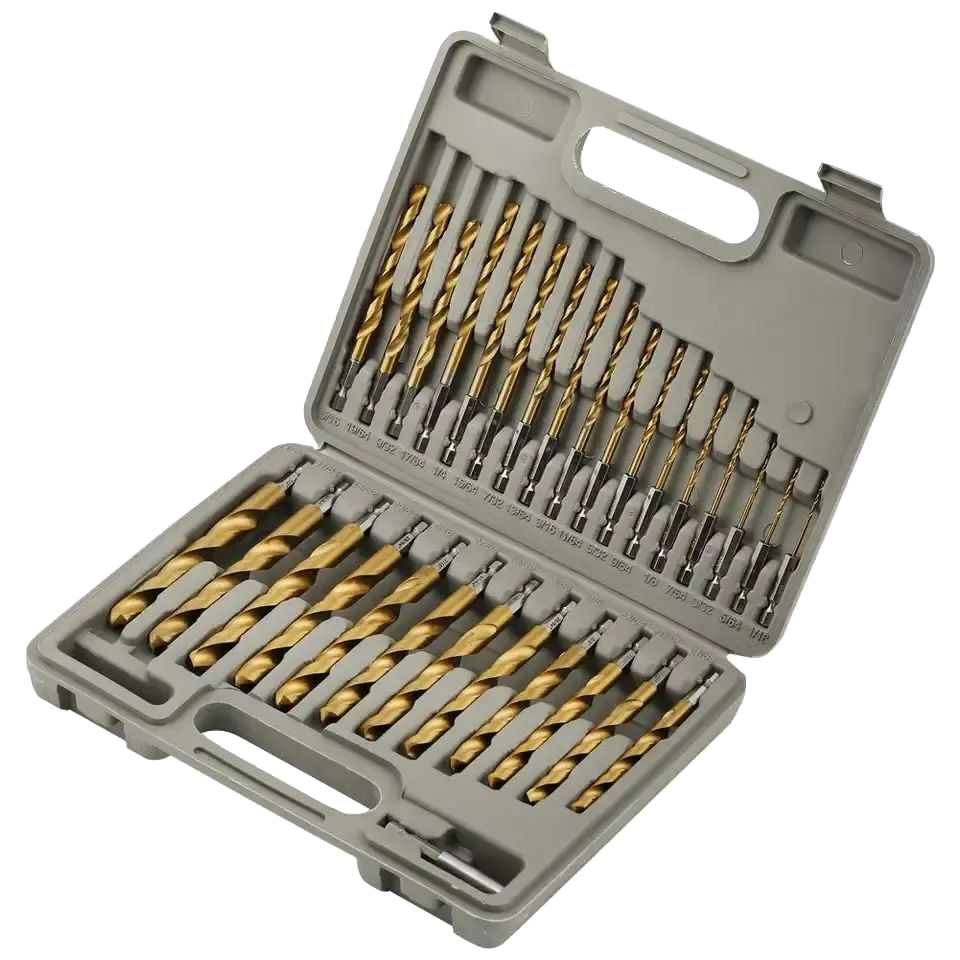
Product Overview
A twist drill is the default hole-making tool and the one every other drilling operation is measured against. Two helical flutes run up the body; where they meet the end face, two cutting lips shear the material and the flutes carry the chips out. It sounds simple, and for a century of general engineering it has been good enough that most of the detail gets ignored — right up to the point where a hole comes out oversize, a bit snaps in stainless, or a 13 mm drill refuses to start where you marked it.
This set is built around three deliberate choices.
- Solid, fully ground M2. The flutes are ground from a solid bar rather than rolled into shape, which is what keeps the point symmetric and the body concentric. An asymmetric point is the number one cause of oversize holes: if one lip is longer than the other, the hole comes out roughly twice that error oversize and the thrust all goes onto one lip.
- A ground point, not a stamped one. 118° conventional as the general-purpose grind, with a 135° split point offered from 2 mm up. Below about 2 mm the web is too thin to split without leaving the centre fragile.
- 1/4 inch hex shank. Sized for the quick-change collets and impact drivers that most site work now runs on. See the caveat in the shank section — hex is not a licence to put a twist drill in a rotary hammer.
Application coverage follows the material spec: alloy and non-alloy steel, cast iron and sintered iron, non-ferrous metals, sheet metal and plastics. That is the honest range of an uncoated M2 jobber drill, and it is wide enough that most shops never need anything else for through-holes.
What Is in the Set: the Diameter Ladder
A drill set is only as good as its ladder. Two questions decide whether a set gets used or sits in the case: does it contain the clearance sizes you actually need, and can you find the size you want without squinting at a flute?
The 25-piece metric ladder
1.0 – 13.0 mm in 0.5 mm steps is the standard industrial configuration and the one we recommend as a default:
1.0 · 1.5 · 2.0 · 2.5 · 3.0 · 3.5 · 4.0 · 4.5 · 5.0 · 5.5 · 6.0 · 6.5 · 7.0 · 7.5 · 8.0 · 8.5 · 9.0 · 9.5 · 10.0 · 10.5 · 11.0 · 11.5 · 12.0 · 12.5 · 13.0
The reason 0.5 mm steps matter is that clearance holes are not round numbers. A metric bolt needs a hole about 0.4 to 1.0 mm over its nominal size, and the ISO 273 medium series is what most fabrication uses:
| Bolt | Fine (mm) | Medium (mm) | Coarse (mm) | Bolt | Fine (mm) | Medium (mm) | Coarse (mm) |
|---|---|---|---|---|---|---|---|
| M3 | 3.2 | 3.4 | 3.6 | M12 | 13.0 | 13.5 | 14.5 |
| M4 | 4.3 | 4.5 | 4.8 | M14 | 15.0 | 15.5 | 16.5 |
| M5 | 5.3 | 5.5 | 5.8 | M16 | 17.0 | 17.5 | 18.5 |
| M6 | 6.4 | 6.6 | 7.0 | M18 | 19.0 | 20.0 | 21.0 |
| M8 | 8.4 | 9.0 | 10.0 | M20 | 21.0 | 22.0 | 24.0 |
| M10 | 10.5 | 11.0 | 12.0 | M24 | 25.0 | 26.0 | 28.0 |
Notice that the medium column lands on half-millimetres almost every time — 4.5, 5.5, 6.6, 9.0, 11.0, 13.5. A set in whole-millimetre steps forces you to either ream or accept slop, and a set in 1 mm steps for the small sizes leaves you without a pilot for M3. That is the whole argument for the 0.5 mm ladder.
The inch-and-metric trap
If your market runs imperial fasteners, a metric set will bite you, and it is worth knowing exactly where:
| Nominal | Decimal inch | Exact mm | Nearest metric bit | Error | Verdict |
|---|---|---|---|---|---|
| 1/4″ | 0.250 | 6.350 | 6.5 mm | +0.15 mm | Acceptable for a clearance hole, not for a fit |
| 5/16″ | 0.3125 | 7.938 | 8.0 mm | +0.06 mm | Close enough for almost everything |
| 3/8″ | 0.375 | 9.525 | 9.5 mm | −0.03 mm | Undersize — use 9.5 for a press fit, 10.0 to clear |
| 1/2″ | 0.500 | 12.700 | 13.0 mm | +0.30 mm | Too loose for a bolted joint; buy a 12.7 mm bit |
| 3/4″ | 0.750 | 19.050 | 19.0 mm | −0.05 mm | Undersize; use 19.5 or 20.0 to clear |
The rule: for a clearance hole, rounding up by less than 0.2 mm is harmless. For anything that locates — a dowel, a shoulder bolt, a reamed fit, a threaded hole you intend to tap — buy the exact size. And if you are pre-drilling for a reamer, the standard allowance is about 0.2 mm under finished size up to 12 mm (10 mm reamer → 9.8 mm drill).
Reading the case, not the flute
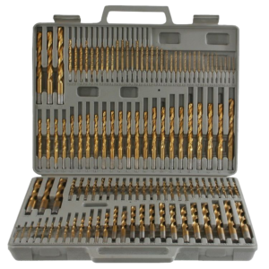
The cheapest failure in a drill set is a case with blank slots. Sizes stamped into a flute become unreadable the first time the bit gets hot and oily, and then every size change becomes a guess against a caliper. An indexed case with the size printed next to each slot keeps the set complete — and a set with one missing size is a set that stops being used.
Anatomy of a Twist Drill
Six features decide how a drill behaves, and every one of them has a characteristic failure. Knowing which feature has failed tells you whether to regrind or bin the bit.
| Feature | What it does | The number that matters | What goes wrong |
|---|---|---|---|
| Point / cutting lips | Does the actual shearing. Two lips, one per flute. | Included angle 118° or 135°; the two lips must be equal in length | Unequal lips → oversize hole and one-sided thrust. Chipped corner → heat and rapid wear. |
| Chisel edge (web) | The blunt centre. Does not cut — extrudes. | Length ≈ web thickness, typically ~0.10 × D | Contributes ~50% of thrust. Worn or too wide → walking, heat, poor centring. |
| Flute (helix) | Forms the rake face and carries chips out. | Helix angle 30° for type N; 12–22° slow, 35–45° fast | Packed flutes → heat, then a snapped bit in deep holes. |
| Margin / land | The narrow ground strip along the flute edge that guides the bit and sizes the hole. | Width ~0.1–0.3 mm per land | Worn margins → undersize hole, burnished wall, squeal. |
| Body clearance (back taper) | Reduces the body diameter behind the margin so only the margin rubs. | ~0.02–0.08 mm per 100 mm | No clearance → the whole body rubs, temperature climbs, the bit seizes. |
| Web | The central spine that gives the drill its torsional strength. | Thickens towards the shank (web taper) | Thinned too far → the point splits on breakthrough. Too thick → high thrust. |
| Shank | Transmits torque and locates the bit. | h8–h9 on diameter; straight, 3-flat, hex or Morse taper | Slip in the chuck → scored shank, runout, oversize hole. |
| Heel | The trailing part of the end face, behind the lip. | Must sit lower than the lip — that gap is the relief angle | Relief too small → the heel rubs and no amount of pressure makes it cut. |
The Point: 118° Against 135°
Point angle is the included angle between the two cutting lips, measured across the tip. It is the single most quoted number on a drill and the most misread one, because it gets asked to do two jobs at once: it sets how the drill cuts, and it is used as shorthand for whether the drill has a split point. Those are separate things.
| Dimension | 118° conventional | 135° conventional | 135° split point |
|---|---|---|---|
| Point shape | Sharper, longer lips | Flatter, shorter lips | Flatter, plus two secondary edges at the centre |
| Chisel edge | Full web width, extruding | Wider still — flatter angle lengthens it | Cut away; two cutting edges replace it |
| Axial thrust | Baseline | Higher than 118° | 25–50% below baseline |
| Starts without a centre punch | No — it will skate | Worse — flatter point, wider chisel | Yes, on flat, curved and inclined surfaces |
| Lip strength | Thinner, chips in hard material | Stronger, resists chipping | Strongest — the corner is supported |
| Heat at the corner | Concentrated | Spread over a wider edge | Spread, plus less extrusion heat at the centre |
| Best materials | Mild steel, cast iron, aluminium, brass, copper, plastics, wood | Hard and work-hardening steels | Stainless, alloy and heat-treated steel, titanium; also general CNC work |
| Chip form | Long ribbons in ductile material | Wide ribbons | Breaks into shorter pieces; easier evacuation |
| Cost | Lowest — one grind | Same as conventional | Higher — an extra grinding operation |
| Regrinding | Easy freehand or on a simple jig | Easy | Needs a jig or a dedicated sharpener to reproduce |
The practical rule
If you drill mainly mild steel, cast iron, aluminium and plastics, fit 118° and use a centre punch. If stainless or alloy steel is more than an occasional job, fit a 135° split point and stop carrying a centre punch. For a mixed shop the split point is the safer default even though it costs more, because the failure mode it prevents — a bit walking off your mark — is the one that scraps the workpiece.
And one thing the table makes plain: a 135° point is not automatically a split point. Plenty of cheap 135° drills are ground conventional with no split at all, which gives you the worst of both — more thrust than 118° and no self-centring. If the listing does not say “split point”, assume it does not have one.
The Chisel Edge, and the Thrust Paradox
Here is the question that confuses buyers, and the answer that resolves it: does a 135° drill need more pressure or less?
Both answers are correct, for different drills. Increasing the point angle on a conventional grind lengthens the chisel edge and puts more of the work into extrusion, so thrust goes up. Splitting the point removes the chisel edge entirely and replaces it with cutting edges that have positive effective rake, so thrust goes down — by a quarter to a half in published comparisons. Most of the contradiction you will read online comes from articles that treat “135°” and “split point” as the same thing.
How much of your push is being wasted
The chisel edge runs at a large negative rake angle — effectively a tiny flat chisel being pushed into the work. Material under it is not sheared into a chip, it is plastically displaced. The specific pressure in that zone runs several times the specific cutting force of the lips, because there is no rake face to speak of.
| Web thickness as a share of diameter | Chisel edge share of total thrust | What it means in the shop |
|---|---|---|
| ~10% (thin web, typical of a good HSS drill) | Low — a well-behaved drill | Starts reasonably, moderate feed pressure |
| ~20% | Around 50% | The standard case: half your feed force makes no chip |
| ~30% | Roughly doubles | Hard starting, strong walking tendency, rapid heat |
| ~40% | Roughly quadruples | Typical of a worn drill re-ground to a short stub, or a cheap thick-web blank |
The experimental evidence is unusually direct. In the classic University of Illinois twist-drill tests, opening a pilot hole equal in diameter to the web — so the chisel edge had nothing left to extrude — reduced measured thrust by 59 percent while torque was barely affected until the pilot exceeded about 15 percent of the drill diameter. That is the purest available demonstration that the chisel edge is a thrust device, not a cutting device.
Why you should care about thrust specifically
- Small drills break from thrust, not torque. Below about 3 mm the limiting failure is column buckling under axial load. Halving thrust roughly doubles the practical feed you can apply before the bit snaps.
- Extrusion is heat without a chip. Work done displacing material at the centre becomes temperature and nothing else. It is the reason a drill can be smoking hot while producing almost no swarf.
- Thrust is what makes a drill walk. Until the lips bite, the drill is a column with a blunt end being pushed against a surface. Reduce the blunt end and you reduce the walking.
- Thrust is what a worn drill spends. As the chisel edge rounds off it behaves like a progressively wider chisel, so thrust climbs while the holes get worse. Rising feed pressure on a familiar material is a sharpening signal, not a reason to push harder.
This is also why web thickness grows towards the shank. The drill needs torsional strength, so the manufacturer thickens the web along the body — which means a drill re-ground repeatedly into a stub ends up with a thicker web at the point and therefore higher thrust than when new. It is a real, if slow, form of degradation.
Web-Thinning Families: X, N, R and S
“Split point” is the umbrella term; the specific grind matters. Four families cover almost all shop work, and they are not interchangeable.
| Dimension | X-type (classic split) | N-type (four-facet) | R-type (rounded relief) | S-type (steep split) |
|---|---|---|---|---|
| How it looks | Two narrow splits either side of the centre, leaving twin central tips | Two secondary facets meeting on the axis, forming a true point | Chisel shortened and radiused, no sharp split corners | Steeper split with a supporting heel behind it |
| Thrust reduction | Large | Large | Moderate | Moderate to large |
| Self-centring | Excellent | Best — the point is a true point | Good | Good |
| Tip strength at breakthrough | Moderate | Moderate | Best — no sharp corners to chip | Good — the heel supports it |
| Chip breaking | Good, short chips | Good | Fair | Fair |
| Reproducible by hand | Yes, on a bench grinder with practice | Hard — needs a fixture | Moderate | Hard |
| Best for | General steel and stainless, hand-held drilling | Position-critical holes, CNC, repeat regrinds | Cast iron, rigid setups, where tip strength matters more than minimum thrust | Small diameters and thin webs |
Standardise on X for a general-purpose set and N where hole position is critical. Keep R in mind for cast iron, where the abrasive, short-chip material rewards a strong tip over minimum thrust, and S for small diameters where the web is too thin for a conventional split.
One limit applies to all of them: there is a floor on how far you can thin the web. The web is what stops the drill splitting up the flutes under cutting load. Over-thin a web on a drill that sees high feed or intermittent cut and the point opens up. The usual target is a remaining chisel length of about 2–6 percent of diameter, depending on the material group in the next section.
Point Geometry by ISO Material Group
Rather than memorising materials one at a time, use the ISO workpiece groups. They map cleanly onto the three numbers you actually set: point angle, lip relief, and how far to thin the web.
| ISO group | Typical materials | Point angle | Lip relief at the margin | Preferred thinning | Target chisel length | Cutting speed (m/min) |
|---|---|---|---|---|---|---|
| P | Carbon and low-alloy steel, cast steel | 118–130° | 10–12° | X or N | 3–6% of D | 25–35 below 500 N/mm²; 18–25 at 500–800 |
| M | Stainless steel, austenitic and duplex | 130–140° | 12–14° | X or N, polished rake | 2–5% of D | 8–12 with HSS-E |
| K | Grey, nodular and malleable cast iron | 118–130° | 8–12° | R or N | 4–7% of D | 15–25 |
| N | Aluminium, magnesium, copper, brass, bronze | 90–110° | 12–16° | N or light X | 2–4% of D | 40–80 (Al), 40–60 (brass), 30–40 (Cu) |
| H | Hardened steel | 135–140° | 8–10° | N, four-facet | 2–4% of D | 10–15 with HSS-E |
| Plastics | PVC, acrylic, nylon, phenolic, GRP | 60–90°, often with reduced rake | 12–20° | Light N | — | 20–40; 10–20 for reinforced grades |
Two entries deserve a word. Group N at 90–110°: a sharp point in aluminium produces a clean entry with less burr, and a generous lip relief of 12–16° is what stops the bit grabbing and screwing itself into soft material. Plastics at 60–90° with reduced rake: the aim is to scrape rather than bite. A sharp 118° point in acrylic or polycarbonate will grab on breakthrough and crack the sheet; a flatter point with little or no positive rake cuts cleanly. That is the same anti-grab logic a step drill uses in thin sheet, one reason a step drill set is worth having alongside this one.
On coolant: for group P water-soluble flood is standard, and peck for anything past about 3×D. Group M wants coolant delivered to the point under pressure rather than dribbled on top — starving it is how you work-harden the surface you are trying to cut. Group K is usually run dry with air, because cast iron swarf plus water makes a grinding paste. Group N wants flood or mist, mainly to stop built-up edge on the lips.
Helix Angle: Type N, H and W
The helix angle is the angle of the flute relative to the drill axis, and it is doing two things at once: it sets the rake angle at the cutting lip, and it sets how fast chips climb out. Standard type N is 30°.
| Dimension | Type H — slow helix | Type N — normal helix | Type W — fast helix | Parabolic flute |
|---|---|---|---|---|
| Helix angle | 12–22° | 25–35° (30° standard) | 35–45° | ~30–40° with a much wider flute section |
| Effective rake | Low — a blunt, strong lip | Balanced | High — cuts freely | High |
| Lip strength | Highest | Good | Lower — chips in hard material | Good |
| Chip evacuation | Slowest | Adequate to ~5×D | Fast | Best — the flute is genuinely larger |
| Grab / screw-in tendency | Lowest | Moderate | Highest in thin sheet | Low |
| Best materials | Hard, short-chip and abrasive materials; brass and bronze; thin sheet | General steel, cast iron, most shop work | Aluminium, copper, long-chip soft materials, deep holes | Deep holes over ~5×D, aluminium, anything that packs |
The thin-sheet point is worth stating plainly, because it is where twist drills get a bad name. A steep helix acts like a screw thread. While the point is buried in thick material the flutes are supported and it does not matter. The instant the point breaks through thin sheet there is almost nothing left for the flutes to grip, so they bite and pull the drill through, dragging the sheet up the helix — the classic out-of-round triangular hole and a bent panel. A slow-helix bit, a backing board, and a falling feed pressure at breakthrough all help; a step drill solves it structurally. We cover that comparison on the single step drill bit page.
For deep holes — anything past about 5×D — helix angle alone will not save you. You need either a parabolic flute with genuinely more chip space, or a peck cycle, or both. A jobber drill is specified at 5×D for exactly this reason.
The HSS Grade Ladder
“HSS” on a drill means very little on its own. Five grades are in common use and the gap between the cheapest and the best is not marginal — in continuous steel drilling, a true M2 drill typically lasts several times as long as a low-alloy substitute, and in stainless the gap is wider.
| Grade | Chinese designation | Key alloying | Hardness | Red hardness | Cost index | Specify it for |
|---|---|---|---|---|---|---|
| 4241 | W4Mo3Cr4VSi family, low alloy | Reduced W and V | HRC 56–58 | Softens earliest | 1.0 | Thin sheet, plastics, household sets |
| 4341 | W4Mo3Cr4V | Reduced W and V vs M2 | HRC 58–60 | Limited | 1.2 | Light duty, soft metals, wood, cost-led DIY sets |
| M2 | W6Mo5Cr4V2 / 6542 | 6% W, 5% Mo, 4% Cr, 2% V | HRC 62–65 | Holds up beyond ~600 °C | 1.5 | The general-purpose standard: structural steel, cast iron, aluminium |
| M35 | W6Mo5Cr4V2Co5 | M2 + 5% Co | HRC 64–67 | Still ≥HRC 63 at 620 °C | 1.8–2.0 | Stainless steel, high thermal load, production drilling |
| M42 | W2Mo9Cr4VCo8 | 8% Co, 9.5% W | HRC 67–69 | Usable to ~700 °C | 2.5–3.0 | Hardened steel, titanium, nickel alloys; standard bi-metal hole saw teeth |
Red hardness is the property that decides tool life, not room-temperature hardness. A cutting edge in steel runs above 500 °C within seconds. What matters is whether the steel is still hard at that temperature. M2 holds; 4341 and 4241 start to soften, and once the edge softens it deforms faster than it wears, which is why cheap drills die abruptly rather than gradually.
Cobalt is not free. M35 typically costs 15–25 percent more than M2, so the argument is cost per hole, not cost per bit: if M2 gives 50 holes in stainless and M35 gives 150, the expensive bit is the cheap one. Equally, M42 is harder and less forgiving — it punishes side load and deflection, so it belongs in a drill press or a CNC machine rather than in a hand-held drill.
Two buying cautions. First, the grade label only tells part of the story: carbide distribution, cleanliness of the steel and the heat treatment cycle vary enormously between mills, so ask for the mill certificate when the grade is contractual. Second, M2 is the grade most often substituted in export quotes — a set sold as M2 and made from 4341 looks identical and fails on the first stainless job.
Incidentally, this is why M42 is the standard tooth material for a quality bi-metal hole saw set: the teeth take far more heat per tooth than a drill lip does, and only a high-cobalt HSS survives it.
Solid, Rolled and Ground
The original description says the body is “the production of solid metal”, which points at the right idea — but there are three distinct ways a drill blank becomes a drill, and they are not equivalent.
| Dimension | Roll-forged (HSS-R) | Milled | Fully ground (HSS-G) |
|---|---|---|---|
| How the flutes are formed | Hot rolled into shape, then the body is twisted | Flutes milled from the bar before hardening | Flutes ground from the hardened bar |
| Flute accuracy | Lowest — shape varies along the length | Moderate | Highest — consistent section and rake |
| Concentricity / runout | Poorest | Moderate | Best |
| Point symmetry achievable | Poor | Good | Best |
| Chip flow | Less consistent, more packing | Good | Best — ground flutes are smoother |
| Edge sharpness out of the box | Moderate | Good | Sharpest |
| Cost | Lowest | Moderate | Highest |
| Right for | DIY sets, soft materials, price-led volume | Mid-market general purpose | Production, stainless, anything where hole size matters |
The measurable consequence is runout. A rolled drill that is not concentric cuts with one lip doing most of the work: the hole comes out oversize, thrust is unbalanced, and the drill wears on one side. That is precisely the failure mode the chisel-edge discussion above predicts, and it is why a ground drill is cheaper per hole in anything harder than free-cutting mild steel.
On heat treatment, the sequence that produces those hardness figures is a high-temperature austenitising quench followed by multiple tempers — typically three, in the 540–570 °C band, to convert retained austenite and develop secondary hardness. It is also the reason overheating in service is unrecoverable: if you draw the temper out at the cutting edge, no sharpening brings the hardness back. See the failure section.
Shanks, and the Impact-Driver Caveat
Shank choice is a chuck question, and getting it wrong costs you either slipping or runout.
| Shank | Fits | Torque capacity | Runout | Change speed | Notes |
|---|---|---|---|---|---|
| Straight / cylindrical | 3-jaw chuck, keyless chuck, collet | Limited by chuck grip — can slip under high torque | Best in a collet | Slowest — needs a chuck key or a firm hand | The DIN 338 default. Slip scores the shank and ruins concentricity. |
| Three-flat | 3-jaw chucks, some impact collets | Higher — the flats are driven positively | Very good | Slow | The standard fix for a drill that slips in a chuck. |
| 1/4″ hex (6.35 mm) | Quick-change chucks, impact drivers, bit holders | Good for the size range | Good — not collet-grade | Fastest — one-handed | What this set ships with. Suits site work and rapid size changes. |
| Reduced shank | Lets a large drill fit a smaller chuck | Limited by the reduced section | Good | Slow | How a 20 mm drill fits a 13 mm chuck. The step is a stress raiser. |
| Morse taper | Drill press and machine spindles | Highest — driven by friction and the tang | Excellent | Slowest | DIN 345. MT1 covers 3–14 mm, MT2 14.25–23 mm, MT3 23.25–31.75 mm. |
DIN Length Standards and Depth
Length is a standard, not a preference. Four DIN families cover straight-shank drills, and the one you want is decided by hole depth — because a longer drill flexes more and clears chips worse.
| Ø (mm) | DIN 1897 stub — overall / flute | DIN 338 jobber — overall / flute | DIN 340 long — overall / flute | DIN 1869 extra long — overall / flute |
|---|---|---|---|---|
| 3 | 49 / 16 | 61 / 33 | 100 / 66 | 150 / 100 |
| 4 | 55 / 20 | 75 / 43 | 119 / 78 | 175 / 120 |
| 5 | 62 / 26 | 86 / 52 | 132 / 87 | 195 / 135 |
| 6 | 66 / 28 | 93 / 57 | 139 / 91 | 205 / 140 |
| 8 | 79 / 37 | 117 / 75 | 165 / 109 | 240 / 165 |
| 10 | 89 / 43 | 133 / 87 | 184 / 121 | 265 / 185 |
| 12 | 102 / 51 | 151 / 101 | 205 / 134 | 295 / 205 |
| 16 | 115 / 58 | 178 / 120 | 227 / 150 | — |
| 20 | 131 / 66 | 205 / 140 | 254 / 166 | — |
Jobber is the general-purpose length and the DIN 338 default: a flute of roughly 8–10 × D, rated in practice to about 5 × D of hole depth because beyond that the chips cannot get out before they pack. Stub (DIN 1897) is the one to specify when you want stiffness and accuracy — a stub drill deflects far less, which is why it is the usual answer to a walking problem on a drill press. Long and extra-long are for reach, and you pay for it in deflection and in chip evacuation.
The practical rule for a set: buy jobber, and add a stub set for positional accuracy if you do production work. A jobber drill with 60 mm of stick-out is a cantilever; the same diameter in stub with 25 mm of stick-out is a very different tool in the same steel.
Speed and Feed: the Two Numbers
Drilling has two independent settings and most people only think about one. Speed (cutting speed at the periphery) governs heat and therefore tool life. Feed (advance per revolution) governs chip thickness, and chip thickness is what carries the heat away.
Step 1: cutting speed from the material
These are HSS values in metres per minute. They assume sharp drills, adequate coolant and reasonable rigidity.
| Material | Cutting speed (m/min) | Material | Cutting speed (m/min) |
|---|---|---|---|
| Steel up to 500 N/mm² | 25–35 | Aluminium | 40–80 |
| Steel 500–800 N/mm² | 18–25 | Brass | 40–60 |
| Steel above 800 N/mm² (HSS-E) | 10–15 | Copper | 30–40 |
| Stainless steel (HSS-E) | 8–12 | Plastics | 20–40 |
| Grey cast iron | 15–25 | Reinforced plastics / GRP | 10–20 |
Step 2: turn speed into rpm
n = V × 1000 / (π × D) — with V in m/min and D in mm.
A 10 mm drill in mild steel at 25 m/min: 25 × 1000 / (3.142 × 10) ≈ 800 rpm. The same drill in 304 stainless at 10 m/min: about 320 rpm. Note how violent the change is — going from mild steel to stainless costs you 60 percent of your spindle speed, and trying to keep the mild-steel speed is the most common way a drill is killed in stainless.
Step 3: feed per revolution
Feed is where most hand drilling goes wrong, in the direction of too light. Too light a feed does not cut a chip at all — it rubs, work-hardens the surface and burns the lip. Two continuous curling chips, one per flute, is what correct looks like.
| Ø (mm) | Steel (mm/rev) | Stainless / tough alloy (mm/rev) | Aluminium, brass, plastics (mm/rev) | Feed rate at 800 rpm, steel (mm/min) |
|---|---|---|---|---|
| 1–1.5 | 0.03–0.05 | 0.02–0.03 | 0.04–0.06 | — |
| 2–3 | 0.05–0.08 | 0.03–0.05 | 0.06–0.10 | — |
| 3–5 | 0.06–0.10 | 0.04–0.07 | 0.09–0.14 | — |
| 5–8 | 0.09–0.14 | 0.06–0.10 | 0.13–0.20 | — |
| 10 | 0.12–0.18 | 0.08–0.13 | 0.18–0.26 | ~105 at 0.13 |
| 12–16 | 0.16–0.22 | 0.10–0.16 | 0.22–0.30 | — |
| 16–20 | 0.20–0.26 | 0.13–0.19 | 0.26–0.36 | — |
Feed rate in mm/min is simply feed per revolution × rpm, so the 10 mm example works out at about 105 mm/min in mild steel. On a hand-held drill nobody measures that — you read the chips instead. Dust or tiny flakes means you are rubbing, not cutting. Increase feed, or reduce speed if the drill is bogging.
Four Faces of Bit Failure
Every drill death falls into one of four patterns, and each has a different verdict: regrind, or retire.
| Failure | How you recognise it | Usual cause | Verdict |
|---|---|---|---|
| 1. Chipped outer corner | A bright nick at the lip/margin junction; sudden squeal; the hole wall is torn | Feed too high for the lip strength; too low a speed in hard material; the point exiting through a hard skin or a scale layer; no relief at breakthrough | Regrind only if you can remove the whole lip below the damage. Usually retire — a chipped corner propagates. |
| 2. Burnt edge / lost temper | Straw to blue oxide colour on the lips; the edge deforms rather than wears; it stops cutting in material it handled easily before | Speed too high; feed too light so the lip rubs; coolant not reaching the point; flutes packed so the chips re-cut | Retire the affected length. Regrind past the discolouration is possible but you have lost the hardness in the remaining body too — temper loss is not a surface film you can grind off. |
| 3. Blunt or wide chisel edge | Feed pressure climbs; the bit walks before it starts; holes come out oversize and out of position; thrust is up but swarf is down | Normal wear, accelerated by hard or abrasive material; also the natural consequence of re-grinding a drill shorter, which moves a thicker part of the web to the point | Regrind, and re-thin the web while you are there. This is the failure mode a sharpener fixes properly. |
| 4. Bent shank or cracked flutes | Visible runout when spun; a crack running from the flute root | Side load — usually a hand-held drill at an angle, a workpiece that moved, or breakthrough snatch; or excessive torque on a packed flute | Retire immediately. Never straighten a bent drill: it has yielded once and will break at the same place, and a drill that breaks in the hole is a serious hazard. |
One more signal worth a mention because it is cheap to check: monitor how hard you have to push. Axial thrust scales with wear, so a drill that needs noticeably more feed pressure in the same material is telling you it is dull — before the holes start going wrong.
Three Ways to Stop a Bit Walking
Walking is the drill skating across the surface before the lips bite. It is a chisel-edge problem at root: the blunt centre has to build up enough force to start extruding before the lips are loaded symmetrically, and until then the drill is free to move. Four fixes, in ascending order of how much they cost.
- Centre punch. A dimple gives the chisel edge somewhere to sit, so the lips load symmetrically from the first revolution. It costs nothing and it is still the right answer when hole position matters. Put the punch exactly on the mark — a punch mark that is off by 0.3 mm gives you a hole that is off by 0.3 mm, and a drill will happily follow a bad punch mark.
- Pilot hole. Drill a small hole first, then open it out. The experimental evidence is that a pilot equal to the web diameter removes essentially the entire chisel-edge contribution; in practice a pilot around a third of the finish diameter is enough to stop walking and it also reduces the torque the finish drill sees. Two caveats: the pilot drill must be stiff and short, and on a very hard surface you may need to spot-face first.
- Drill bushing or jig. A hardened bushed plate sitting just above the work constrains the drill physically, so even a walking point cannot go anywhere. This is the production answer when you are drilling the same hole in fifty parts, and it also fixes the deflection problem at the same time. A drill press with the table square and the work clamped gets you part of the way for free.
- Fix the geometry instead. A split point removes the cause rather than the symptom: the centre cuts, so there is no blunt feature to skate and no need for a punch, a pilot or a bushing on ordinary work. It is more expensive per bit and it is why the split point is the recommended specification for anything beyond casual use.
Two supporting habits. Minimise stick-out: chuck the drill as short as the job allows, because deflection at the point is what turns a small centring error into a badly placed hole. And square the spindle to the work — even a split point will skid on a steeply angled entry, and a drill entering at an angle loads one lip and walks regardless of its grind.
Resharpening: the Four Checks
A twist drill is one of the few cutting tools worth sharpening by hand, but only if you hold four things. Get any one wrong and you will produce a drill that is sharp and useless.
- Point angle, correct for the material. 118° for general work, 130–140° for stainless. Check against a drill point gauge rather than by eye — the eye is remarkably bad at this.
- Both lips the same length. This is the one that matters most. Unequal lips put all the thrust on one lip, cut the hole roughly twice the error oversize, and make the drill walk. Measure, do not eyeball.
- Relief behind the lip. The heel must sit lower than the cutting edge, typically 10–14° at the margin. Too little relief and the heel rubs so the drill will not cut however hard you push; too much and the lip becomes thin and chips.
- The chisel edge stays on the axis. After grinding, the chisel edge must be centred and, ideally, shortened. If it is off-centre the drill walks; if it is left full width you have regained sharpness but not the thrust benefit. This is the step a split-point grind adds, and it needs a jig or a dedicated sharpener to reproduce.
On the wheel itself: HSS is a steel, so the correct abrasive is CBN or aluminium oxide — never diamond. Diamond and steel react at grinding temperature and the diamond graphitises, so a diamond wheel is both the wrong tool for HSS and an expensive way to destroy a wheel. Our resin-bonded CBN grinding wheels are built for exactly this job. If you are sharpening carbide instead, that is the reverse case, and it is covered on the carbide-tipped Forstner page.
Be realistic about the economics. Hand sharpening restores the lips but rarely reproduces a split point accurately. If your drills are specified with a split point and you sharpen them freehand, you are quietly converting them back to conventional points and losing the thrust and centring benefit. Either invest in a sharpener with a split-point capability, or treat sharpened drills as general-purpose and keep a dedicated split-point set for work that needs it.
Full Specifications
| Product name | HSS Twist Drill Bits Set |
|---|---|
| Brand | GUSHI (Huzhou Gu’s Imp. & Exp. Co., Ltd.) |
| Body material | M2 high-speed steel, W6Mo5Cr4V2 / GB 6542; M35 (W6Mo5Cr4V2Co5) available on request |
| Hardness | HRC 62–65 (M2); HRC 64–67 (M35) |
| Red hardness | Effective cutting edge retained beyond 600 °C (M2); ≥HRC 63 at 620 °C (M35) |
| Manufacture | Fully ground from solid round bar (HSS-G); milled and roll-forged options quoted separately |
| Standard configuration | 25 pieces, 1.0–13.0 mm in 0.5 mm steps |
| Alternative configurations | 13, 19, 29 and 170-piece sets; imperial, wire-gauge and letter-size ladders; 1–6 mm, 1–10 mm and 1–13 mm ranges |
| Point angle | 118° conventional standard; 135° split point optional, offered from 2.0 mm diameter upwards |
| Point form | Conical (DIN 1412 form A) standard; split point and four-facet grinds available |
| Helix | Type N, 30°, right-hand cut; slow-helix (type H) and fast-helix (type W) options |
| Lip relief | 10–12° at the margin for steel; 12–16° option for non-ferrous and plastics |
| Diameter tolerance | h8 |
| Length standard | DIN 338 jobber; DIN 1897 stub and DIN 340 long available |
| Flute length | Jobber, approx. 8–10 × D; rated working depth 5 × D |
| Shank | 1/4 inch (6.35 mm) hex, quick-change and impact-driver compatible; straight, three-flat and reduced shanks available |
| Surface finish | Bright (uncoated) standard; TiN, black oxide, amber and steam-treated finishes available — see the Ti-coated set, black oxide and amber finish pages |
| Web | Standard web with taper; web-thinned and split point (X or N form) options |
| Recommended cutting speed | Mild steel 25–35 m/min; alloy steel 18–25; stainless 8–12; cast iron 15–25; aluminium 40–80; brass 40–60; plastics 20–40 |
| Recommended feed | 0.12–0.18 mm/rev at Ø10 in steel; scale with the ladder in the speed and feed section |
| Suitable materials | Alloy and non-alloy steel, cast iron, sintered iron, non-ferrous metals (aluminium, copper, brass), sheet metal and plate, plastics |
| Not suitable for | Masonry and concrete (use SDS masonry bits); hardened steel above roughly 40 HRC without HSS-E; glass and ceramic tile |
| Storage | Indexed plastic case with a printed size per slot; metal index case, pouch set and loose bulk available |
| Marking | Size laser-etched on the shank or flute; custom logo and private-label marking available |
| Indicative price | US$8–45 per set depending on piece count, grade and case |
| MOQ | 100 sets standard configuration; 500 sets custom |
| Lead time | 5–10 days standard; 15–30 days custom, after advance payment |
| Payment terms | T/T, L/C, D/A, D/P, PayPal |
| Loading port | Shanghai or Ningbo |
| Quality | 100% inspection before shipment; ISO 9001:2015 quality system — certificate scope to be confirmed at quotation |
Applications
Fabrication and steelwork
Clearance holes for bolted connections, holes in plate, angle and box section, and the pilot holes that precede tapping or reaming. This is the core use, and the ISO 273 ladder in the set section is the reference for hole size.
Maintenance and repair
Drilling out broken fasteners, opening a damaged hole to the next size, adding fixings to existing structures. The 0.5 mm ladder matters here because repair work rarely uses a size you planned for.
Electrical and mechanical installation
Holes in enclosures, backplates, trunking, brackets and mounting rails — generally in thin sheet, where the helix-angle advice above applies. For repeated knockout-sized holes in enclosures, a step drill is the better tool; the two sets complement each other rather than competing.
Automotive and vehicle work
Brackets, panels, chassis plate and bodywork repairs. Mild steel and aluminium are both well within M2’s range; stainless exhaust and trim is where an M35 cobalt set earns its premium.
Plastics and sheet material
Point angle and relief change for plastics — 60–90° with reduced rake — so if plastics are a major share of the work, specify that grind rather than accepting the standard 118°.
Trade, wholesale and private label
The highest-volume configuration in the catalogue. We build to the piece count, diameter ladder, shank type, finish and packaging your market expects; see the OEM section.
How to Drill with a Twist Bit
- Mark, then punch. Cross-centre the mark and punch it, unless you are using a split point on non-critical work.
- Clamp the work. Never hold sheet or small parts by hand. A drill that snags will spin the workpiece, and thin sheet will cut a glove before it cuts skin.
- Pick the speed from the material and the diameter. V from the cutting-speed table, then n = V × 1000 / (π × D). Stainless is roughly a third of the mild-steel speed for the same diameter.
- Chuck short. Take the minimum stick-out the job allows. It is the cheapest accuracy you will ever buy.
- Start square, at low speed. Let the point find the punch mark before you apply full feed and full speed.
- Feed hard enough to make a chip. Two continuous curls, one per flute. Dust means you are rubbing, and rubbing is what burns a lip.
- Peck past about 3×D. Withdraw fully to clear the flutes; packed chips are how bits snap in deep holes. Retract more often in stainless and in material that produces long stringy swarf.
- Coolant to the point, not onto the swarf. In steel, flood or a generous stream of soluble oil. In aluminium, prevent built-up edge. In cast iron, air and run dry.
- Ease off at breakthrough. Reduce feed as the point breaks through so the bit does not snatch — the full method is in the auger bit set guide, and the principle is identical for a twist drill in steel.
- Clear chips with a brush, not a hand. Swarf leaves the flute hot and sharp.
- Deburr and check. A twist drill leaves a burr on both faces. Break the edge with a countersink or a deburring tool before assembly.
- Read the drill before you put it away. Chipped corner, blue lip, rounded centre, bent shank — four checks, ten seconds, and you will not discover a dead bit halfway through the next hole.
Safety
Frequently Asked Questions
What is an HSS twist drill bit set used for?
It is the general-purpose metal drilling set: alloy and non-alloy steel, cast iron and sintered iron, non-ferrous metals such as aluminium, brass and copper, sheet metal, and plastics. In practice it covers clearance holes for bolts and screws, pilot holes before reaming or tapping, holes in plate, angle and box section, repairs and fabrication, and general workshop and site drilling. It is the set you buy first and the one that gets used hardest, because almost every other hole-making job starts with a twist drill making a pilot.
What is the difference between a 118° and a 135° drill point?
118° is the general-purpose included angle and the traditional default for an HSS jobber drill: a sharper point that starts easily in mild steel, cast iron, aluminium, brass and plastics. 135° is a flatter, stronger point used for stainless steel, alloy and heat-treated steels and titanium, where a thin sharp lip would chip. The flatter angle also shortens the contact length at the lip, which is why it survives work-hardening material. Choose by material, not by habit: 118° for soft and general work, 130° to 140° for stainless and tough alloys.
Does a 135° drill bit need more or less pressure than a 118° one?
It depends entirely on whether the 135° bit also has a split point, and this is the single most common point of confusion in drill buying. A 135° conventional point needs more thrust than a 118° one, because the flatter angle lengthens the chisel edge at the centre, and the chisel edge extrudes rather than cuts. A 135° split point needs less, because the split grind replaces the chisel edge with two short cutting edges that have positive effective rake. Measured thrust reductions for splitting or thinning the web are typically 25 to 50 percent.
What is a split point and why does it matter?
A split point is a secondary grind put into the chisel edge region at the centre of the drill, producing two extra short cutting edges that meet on the axis. The chisel edge stops extruding and starts cutting, so axial thrust drops by roughly a quarter to a half. The bit self-centres, so it will start on a flat plate, on pipe, or on a curved surface without a centre punch and without walking. And the chips break into shorter pieces, which evacuate better and reduce heat. Standard jobber drills are offered with a split point from about 2 mm upwards; below that the web is too thin to split without weakening the point.
Do I still need a centre punch if the bit has a split point?
Usually no, and that is the main practical benefit. A conventional 118° point has to build up axial force before the lips bite, and until it does the drill skates across the surface. A split point begins cutting the instant it touches, so on most work you can place the bit and pull the trigger. Centre punch anyway when hole position is critical, when the surface is very hard or scaled, or when you are starting on a steep angle, because even a split point will deflect if the entry surface is not square to the spindle.
What speed and feed should I run an HSS twist drill at?
Set the speed from the material and the diameter. Cutting speed in m/min for HSS: mild steel below 500 N/mm² 25–35, steel 500–800 N/mm² 18–25, steel above 800 N/mm² with HSS-E 10–15, stainless with HSS-E 8–12, grey cast iron 15–25, aluminium 40–80, brass 40–60, copper 30–40, plastics 20–40. Convert with n = V × 1000 / (π × D in mm), so a 10 mm bit in mild steel at 25 m/min is about 800 rpm. Then feed roughly 0.13 mm per revolution at 10 mm in steel, less for stainless and more for aluminium, brass and plastics.
Why do my drilled holes come out oversize?
Four causes, in order of likelihood. The point is ground asymmetrically — if one lip is longer than the other by a small amount, the hole comes out about twice that amount oversize and all the thrust goes onto one lip. The bit is running with too much stick-out or in a worn chuck, so it flexes and wanders. The speed is too high and the feed too light, so the margins rub and burnish instead of cutting cleanly. Or the chisel edge is worn or too wide, which raises thrust and pushes the drill off axis before the lips ever engage.
Can I use these bits in an impact driver?
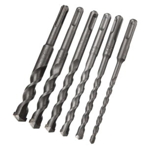
Yes, if the shank is 1/4 inch hex and the bit is intended for impact use — a hex shank is exactly what an impact driver’s collet is built for. Two cautions. Impact delivery is a series of rotational blows, and small diameters under about 3 mm do not have the section to absorb them, so keep the smallest bits in a plain drill or a press. And an impact driver is not a hammer drill: a rotary hammer’s blows are axial and will destroy an HSS point in seconds. For masonry you need an SDS masonry bit, not a twist bit with a hex shank.
How do I know when a twist drill is finished?
Five retirement triggers. The outer corners are chipped, which no amount of regrinding will fix cleanly because you have to remove the whole lip to get below the damage. The cutting edges are blue or straw coloured, which means the temper has been drawn out of the steel and the hardness is gone. The chisel edge is rounded or the point no longer centres, so thrust climbs and the bit walks. The margins are worn along their length, which makes the bit cut undersize and burnish the hole wall. Or the shank is bent or the flutes are cracked — never straighten a bent drill, retire it, because a shank that has yielded once will break at the same place.
What is the MOQ, lead time and OEM support for twist drill bit sets?
MOQ is 100 sets for standard configurations — piece count, diameter sequence, shank type and case. Custom sets, custom diameter ladders, private-label packaging and branded cases start at 500 sets. Standard sets ship in 5 to 10 days and custom sets in 15 to 30 days after the advance payment. Payment is T/T, L/C, D/A, D/P or PayPal depending on the order, and loading is from Shanghai or Ningbo. Samples are available for testing once pricing is agreed; the sample and freight cost is refunded against the first official order.
OEM & Wholesale
Huzhou Gu’s Imp. & Exp. Co., Ltd. manufactures and exports the GUSHI range of drilling, cutting and surface-preparation tooling from Zhejiang, China, supplying importers, distributors, tool brands and private-label programmes in more than 20 countries.
For this set we can customise:
- Set configuration: piece count, diameter ladder (metric, imperial, wire gauge or letter), and case layout. 13, 19, 25, 29 and 170-piece sets are standard production options.
- Grade: M2 as standard; M35 cobalt for a stainless-capable premium version; 4341 for price-led volume programmes where the application supports it.
- Point geometry: 118° or 135°, conical or split point, X or N web-thinning form, and material-specific relief angles.
- Finish: bright as standard, plus TiN, black oxide, amber and steam-treated — see the Ti-coated set, black oxide, Ti-coated and amber finish ranges.
- Shank: 1/4 inch hex, straight, three-flat or reduced, matched to the chuck type your market uses; impact-rated torsion-zone versions on request.
- Branding and packaging: laser-marked sizes and logos, printed sleeves, colour boxes, blister cards, blow-moulded and metal index cases.
- Order terms: MOQ 100 sets standard and 500 sets custom; 5–10 days standard lead time and 15–30 days custom; T/T, L/C, D/A, D/P and PayPal; loading from Shanghai or Ningbo.